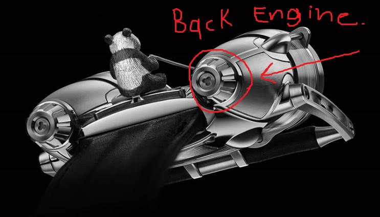
Our mission (we have to accept it) is to model any watch that catches our fancy. So I have decided to try and realistically model this one:


Now "can you model this" you ask? My response, "Errrr, I'm not sure; but I'm going for it!".
Alright, so I started by creating a poly plane and then clicking and dragging a panda watch photo onto it.
.JPG)
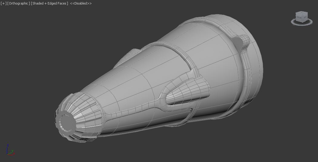
Next I made a standard cylinder and started blocking out the engine portion of it.
.JPG)
.JPG)
I am trying to add the necessary detail to back of the engine.
So I started to add edge loops and pull some geometry around to try imitating the back of the engine.
.JPG)
Then I thought to myself, "do I really want to spend lots of time rotating the back engine and try to raise edges so that it matches the first raised ridge?". Is there another way to do this? I have an idea...
DUPLICATION!!!!!!
.JPG)
Ehhahahaaha, ten minutes into the process I have already slightly changed plans. I realized that the spaces in between the the ridges would be too large so I deleted the "faces shown" in the picture, did a rotation duplication of the mesh and now it looks better.
.JPG)
Now I will start welding!!!
Awesome, it only took 7 minutes! Here is what it looks like at the moment.
.JPG)
.JPG)
It's starting to come together, but I still need to make it look a bit more rounded.
.JPG)
I spent the next hour fixing some of the geometry by adjusting lots of vertices.
.JPG)
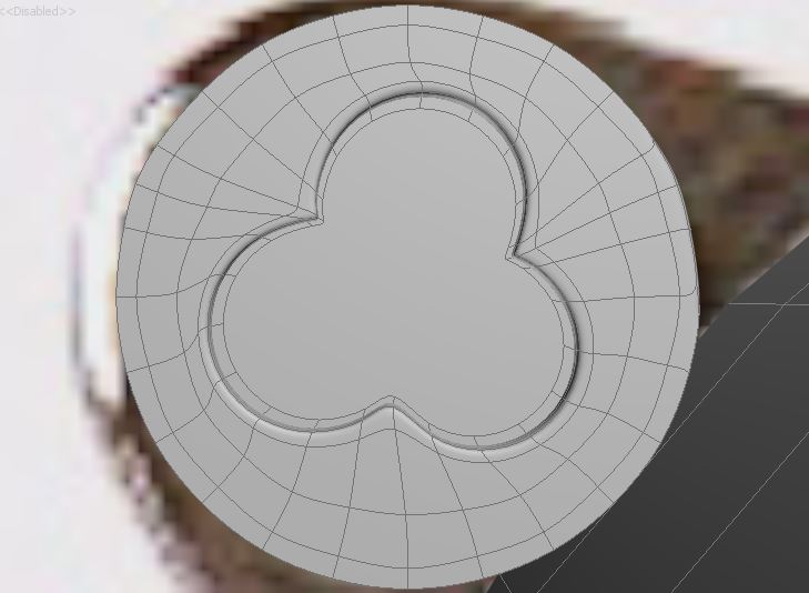
Pretty much done, but I need to figure out how to make the "Mickey-Mouse" shaped screw shape in the center. I may bring it into Maya later and use the "project curvature tool" to get the shape I am looking for; then it would just be a simple matter of using extrude to push the shape into the geometry.
Back Cap of Watch
.JPG)
I tried to move on to middle part of the engine, but I got stuck. I have been learning in programming recently that if you have a big problem to solve it is better to break it up into smaller pieces and then put it back together; I will attempt to do this with my 3D model. I decided to work on the front cap pieces next. I am lucky that this watch seems to have made quite the impact; there are lots of pictures of it from multiple angles.

Look at my research haha!
.JPG)
I used a top perspective to help me know what size to model the front caps.
.JPG)
I started making the clock face.
.JPG)
Here it is with the picture reference turned on transparent.
.JPG)
Well I am going to take a break from all this modeling (I modeled for 8 hours today for this (including screenshots taken and blog updating)).
Alright, I have been working on and off on the panda watch for over 15 extra hours since last. I wasted a lot of time trying to figure out how to wrap that silver metallic band around the cylindrical mesh. Here are a couple things I finished.
I started working on the front left cap of the watch.

This is where I am right now (I also added the glass lens, which I will texture later)(I'm mostly done).

I then tried to finish the front right cap of the watch.

I would say I'm mostly finished with it.

Those bands that you see that are wrapped around the cylinder took a lot longer than I wanted. Mostly because I was trying to make them penetrate deeper into the cylinder (pulling and rotating lots of edges and vertices). It keeps looking a little bit better though.
.JPG)
As you can see I have gone crazy with throwing pictures on polygon planes (the more references and angles to model off of the better).

Today, I started by working on the rounded hill-looking portion of the front band. Here are some reference pictures used.


Surprisingly this also took a bit longer than I wanted it to(maybe 3 hours!). I cut a cylinder in half and then "shift + clicked and dragged + and scaled outward" the bottom border to get the shape. I then deleted the corresponding faces from the front cap band, attached them, and merged the vertices together (it wasn't merging them correctly so it took some time to problem solve what was wrong). The "Weld" vertices option wasn't working so I used "Target Weld" instead.

I think I will now try to work on the screw intersecting through the rounded hill of the band. I suspect that I will have to use "booleans/difference" to get the mickey mouse shape indention in it. Here is what the whole watch looks like as of now (not much of a difference).
Okay, this is going to sound ridiculous, but over the last 5 hours I was only able to finish the screw, make a few more adjustments to the cylindrical watch body, and make the pole connecting two of bands. Here, I will show you.
First I decided to rotate the silver bands around the watch so that it would match the same direction as the rounded hill of of the front band.


I then moved on to the screw, which took way longer than I thought it would (to make it look right that is). Here is what I did.

Made a small cylinder and adjusted it to the size of one of circle indentions. I then duplicated the cylinder, put them in the correct position, and attach them all to each other. Lastly, I intersected into the screw the portion of it I wanted to delete.

I didn't know how to use the booleans tool in 3ds Max like I did in Maya. I looked it up and thought I would share it with you just in case you don't know how to do it either. Normally, the "Create" panel is set to "Standard primitives" so if you click on it and go to the third option in the drop down menu you will find "Compound Objects". Inside you will see the "Boolean" option. In my case, click on the object you want to subtract from and then click "Boolean".

Then click on "Pick Operand B" and click on the object you are using as the "subtractor".

You can see that the portion of the triple cylinders that was intersected into the screw mesh was deleted from the screw. There were a couple remains that had to be deleted and some vertices to be readjusted.

Here is the cleaned insides of the screw. Now you might be thinking to yourself, "Hey, it's easy after this. All you have to do is smooth the mesh to get the perfect rounded look you want"; wrong! I thought the same thing initially, but when I when smoothed the mesh it smoothed it all messed up-like.

So I needed to find a way for it to smooth correctly. I found a way, it may not be the best way, but here is what I did. I selected the inside bottom faces and deleted them (That's right you heard me!).

I then grabbed the border of the gaping hole and "shift + clicked and dragged + and scaled" inward a little (I did this to get a sharper inside edge). Then I used the "Cap" option to close off the rest of the hole. Besides getting the sharper edge I wanted, it also deleted a lot of vertices and lines inside that I didn't need (this can also can make UV Mapping less painful).

Unfortunately, I was not able to close the outside hole as easily. You can go ahead and "Cap" it off like the other gaping hole, but when I did that it covered the opening of the triple cylinder hole I just cut into the screw. I was going to have to merge some more vertices!

There were 26 outward vertices on the triple cylinder indention, but only 12 vertices on the outside of the screw. Because of this I had to add 14 extra lines (edge loops) using the "Connect" tool. I thought that it would be fine to just add the lines on the inside, but I was wrong!

It did round it off a bit more, but was still a bit jagged on the edges. I had to go back and add all the corresponding lines on the outside of the screw as well.

Here is the cylinder piece with extra lines added on the outside.

When I smoothed the mesh it still looked a bit jagged, so I selected every other vertices (the middle, slightly lower vertices) around the outside of the screw and used the scale tool to scale it outward and make it a bit more round.

It is not perfectly round on the outside, but trust me it looks much much better than it did when I was initially smoothing the mesh. Here is the completed screw shape.
Here is a closer look at the sharp inside edges that I was going for inside of the screw.

Well, making that screw was a pain, but the beauty of making one nice screw is that now I can duplicate it to the other 12 or so places on the watch that have the exact same screw shape. Here is the current look of the the left watch engine. (Well, I spent about 8 more hours today on this thing; I'm going to call it a night).

Hello everyone, tonight I modeled a bit more (about 3 more hours). Here is what I did. I noticed when I duplicated/rotated the first part of the silver-wrap-around-hill-band that it didn't match up properly with the bottom right screw in the front. So I had to duplicate/rotate the whole thing, delete part of the geometry, and then weld more edge together. Here are some images showing this.
This is how it looks lined up from the top. (It is hard to get everything perfect because all of the pictures are in slightly different angles).

As you can see, the inside hill is not lined up with the screw in the front.

Here is the picture I looked at that made me make some changes.

I duplicated part of it and then deleted the geometry that didn't match up with the inside bottom screw.

I welded the corresponding vertices and aligned the silver rod with the hill and the screw.

I also forgot to mention that I also modeled the front shiny golf-tee looking object.


Okay all I am back to modeling this thing. I have spent another 4 hours tonight so far (it is due tomorrow morning so I am not sure how I am going to finish it in time). However, I can only continue working and hope for the best. Here is the next portion I did.
As you remember me mentioning before, I said that the front right cap watch face wasn't quite finished. It didn't have any numbers!

So I started looking up where to create text in 3ds. I found it under the splines menu.

I typed the numbers (individually) into the text box and created all the numbers I needed. I proceeded to try to find a slightly close font match to the clock's numbers. Here is what it looks like now.

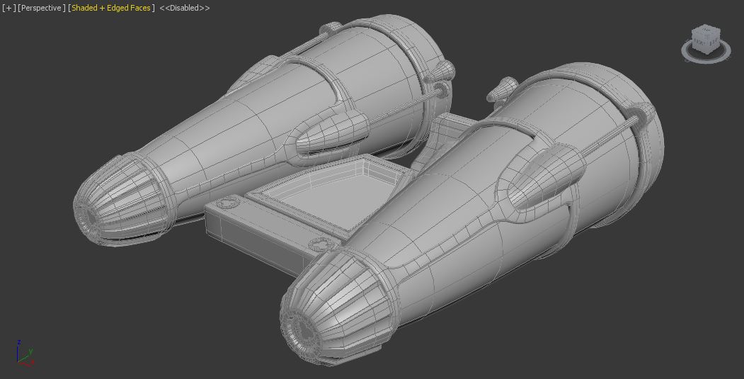
I figured it was finally time to duplicate the engine to the other side and mirror it. I used the "Mirror" modifier so that it would flip the engine perfectly in the 'x' axis; however, I ran into yet another problem! Apparently if you are smoothing your mesh using "NURMS Subdivision" and then you mirror your mesh it will subdivide the mesh a second time! This can be a problem if you want to later weld your edges together since your duplicated mirrored object now has a non matching number of vertices.

Luckily, I found a solution. Once I selected everything and "shift + clicked and dragged" (duplicated) my object over, I went through all my duplicated objects and turned off the "NURMS Subdivision" option. Then I tried mirroring the mesh and positioning it where I wanted. After I "collapsed" the mirror modifier on all my objects in the modifier menu I tried to use the "NURMS Subdivision" on all my objects again. It worked! Now my two engines have the same amount of edgeloops, faces, and vertices.
Here is a look at them from different positions.


Next I looked at the middle portion connecting the two engines together and noticed that the panda was sitting on a little bench of some kind.

It was pretty simple to model (just a basic cube smoothed with some added edgeloops). I was able to reuse the mickey mouse shaped screws too.

Right next to the panda seat there is a glass chamber below it filled with gears. I built the outer part of the glass chamber, but I haven't built any of the gears yet.


Before I continued I noticed that my work space was quite the mess.

It can get kind of confusing sometimes when you have picture references or pieces of geometry floating everywhere in your scene. In order to get around this you can always make layers (kind of like making layers in Photoshop or Illustrator) so that you can hide certain layers.

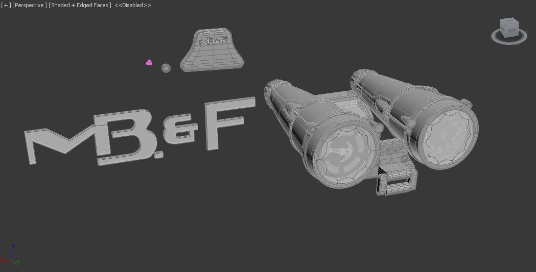
I started working on the front panel next; it shouldn't be terribly difficult (hehe I changed my mind later).

I could continue, but my body is starting to shut down haha. Only getting about 2 hours of sleep in 48 hours isn't very fun. I will try to continue tomorrow, we shall see what my professor says. I started working on the front panel's joint that will eventually hold the watch's band. I worked for another 4 hours since my last hours count. Anyways, here is the current status of the panda watch.
Amount of Time Spent So Far: 42 Hours
Well hello again everyone. It is currently 2:52 am (Saturday morning) and I have been in the Mac Lab for about another 5 hours. My project of course will be considered late, but my teacher was still gracious and not too harsh; so nothing more can be done, but continue until I finish. Here is what I have been working on tonight and the difficulties I have been having.
I continued to work on the front panel and tried to get the engraving signature depressed into the metal. Here is the reference picture I used.

Here is what mine looks like.

This is what I did. First I went to the text tool and typed out the letters individually looking for fonts that matched as closely as possible to the watch design. The fonts did not match perfectly of course so I needed to go into vertice tool to translate (move) the vertices around to get the correct shape. After I got the correct letter shapes I wanted, I attached all the text meshes together into one.
I then got into the tricky part of trying to make it suitable for subtracting from the from the front panel mesh. Let's just say I wasted a lot of time trying a few things and I will tell you what I would not recommend trying (so you will not waste as much time as I did).
First and foremost, I would not (repeat) would not try to duplicate the the text, "shift + click and drag" the borders to the center,
and weld the vertices together. Even though you can technically grab all the middle points at once (I did) and try to merge them in one go, it is difficult for Max to know exactly what points to weld to. When I tried, it ended up merging some points and when I tried to increase the welding parameter to weld everything at once it welds almost all the points together to almost one point.
This next way worked out better. You can just grab the regular border of the text and then "shift + click and drag" the geometry out to the thickness you want. After you pull it out find the "Cap" option in the edit borders menu to close the mesh up. I also added some edgeloops to the edges just in case I would try to smooth things later.
Let's just say that I didn't get it to work (smooth). If you remember above the process I mentioned to model the shape I wanted for that mickey-mouse-shaped screw, it was indeed a tedious process. If I wanted to get that same effect, I would have to do that with the text shape subtracted from the mesh. This is possible, however, the more vertices that your geometry has that you subtract from another mesh the more time consuming and difficult this can become. Even if you try to delete the inside faces, grab all the inside borders, and shift + click and drag, the geometry inward, and weld the vertices together, it isn't easy. Usually some of the lines and vertices get tangled inside various portions of the mesh, forcing you to manually readjust their positions.
After trying for awhile, and getting this (screenshot below) when I smoothed it, I gave up on it, deciding that the non smoothed mesh didn't look too jagged and didn't necessarily need the extra smoothing.
Here is what it looks like without the smoothing (not bad) after I cleaned up some of the stray lines and vertices. I would suggest that if it is taking you hours to do something that you originally thought was easy to possibly move on or to try another process to model the shape you were looking for.
I also modeled part of the watch band frame; just used a combination of cylinders and cubes.

Here is a current look at the models in my scene. As you can see, it is sometimes good to keep spares (duplicates) of your original model so that just in case you want to try something (and you run out of undos to get you back to where you were) you can always try again. I probably duplicated the front panel over 5 times to try different modeling methods. I am also keeping spares of the logo and screw so that I can reuse them on different parts of the model later.
Good evening again. It is currently 9:30 pm Saturday (April 6th) (Why I am giving you all this information, I don't know). I have gotten to work on the watch for about 2 more hours today and will try to work on it for awhile tonight. Here is what I worked on today.

I noticed from looking at various angles of the watch clasp that the two cylindrical pieces on the side were the not exactly the same size on both ends. The bottom half was a bit wider, so I fixed it.

There were also screws depressing into the metal (I have put the screws in place, but haven't tried to depress them in yet).

I then started working on the leather watch band. (Unfortunately all the pictures I can find of the watch do not show the full leather strap).

This is what I have modeled of the watch band for the moment.

Next, I moved on to try and close the gap between the two engines. I duplicated the outer glass chamber and then scaled it in the 'x' and 'y' axis's. I realize that now that I have made the floor I will probably have to tweak other parts of the geometry again. Here is what it looks like.
Reference picture for the floor of between engines.

Luckily, this portion of the model was not hard to make. If you can effectively use a previous piece of geometry to make another part of you model by all means do it.

Here is what it looks like connecting the two engines (I am sure it will need more tweaking later).

I noticed that the front part connecting the watch pieces together covered and intersected with the front panel. So I started modeling the front silver part.

Granted I may have to fix the shape a little bit, but I think it mostly works for now.


As you can see, my work space is starting to get even more cluttered with random extra pieces of geometry. I am starting to get closer and closer to being done though.

I wanted to fill in that last gap between the engines. There was another solid glass panel that I had to install.

I just built a cube, aligned it with the metal floor, added some edgeloops, and then smoothed it. Yay! No more gaps in the middle. I didn't model anything inside of the glass casing though.

Here is the current status of the watch (it's looking better).

Alright, now if you remember before I didn't complete the band around the front watch caps.

To see how it wrapped around the bottom I had to find a picture that showed the underside of the watch. It was the only underside picture that I could find (currently), it's confusing, but I used it as a reference for my model anyways.

Then I decided to model a pair of handcuffs, just because I could. (No, no, of course that isn't what the silver wrap around band looks like).

Okay, here is what it looks like wrapped around the two front caps.

It doesn't look half as bad when you add the other objects in.
.JPG)
.JPG)
I have been looking at the bottom of the watch and I think it will take me a little bit of time to figure how to model it all right. I modeled a little bit more of the watch band frame, but not enough to document (show screenshots of) yet. It is now 3:30 am, so I think I will call it a night, but everyday I get a little bit closer to finishing the menace known as the panda watch. I modeled for about another 6 hours tonight.
Current Amount of Time Modeling Watch Thus Far: 55 Hours

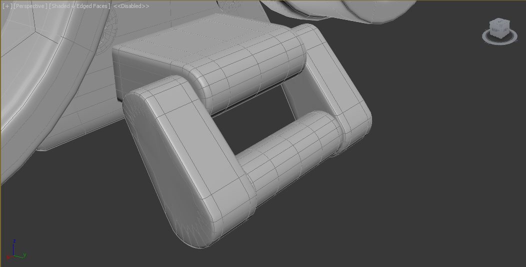
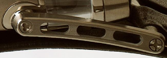
Good morning! It is now 3:58 am and I have worked on the watch for about another 5 hours. I had a lot of difficulty with this next piece of geometry. I consider the piece mostly done, but I still need to find out how to bend it correctly (I tried the "Bend" modifier with no luck).
This is what I attempted to model.
I started with part of a welded cylinder/cube combo and then duplicated it, rotated it 180 degrees, and then welded it together.

I messed with the shape a bit more; adding edgeloops and extruding the edges of it out a bit. I then duplicated the shape 4 more times. With one of the duplicates I subtracted it from the main mesh (the original shape) using "Boolean". With the other three pieces I shrunk them, put them in the correct position, and then subtracted them from the mesh (used Boolean again).

Here is what it looked like.

I think one of the biggest problems that you may have when using the "Boolean" option is smoothing issues (as seen below). So I grabbed the inside faces and "shift + click and dragged" them to the side (as seen above).

Once I deleted a few more of the faces from the duplicate I had only the three inner ringed portion of the geometry left. To sum up what is to come next: I did a lot of selecting borders, "shift + click and dragging", welding of vertices, moving of vertices, and banging my head against a wall to get this desired shape.

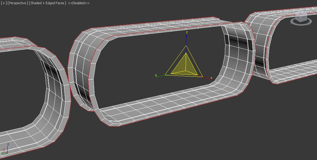

I did the same thing with the outer portion of the side steel frame. This part is really two separate pieces of geometry, but I tried to intersect them the best I could to make them look like one piece.

They will be attached to the front metal of the frame and will look something like this (I know I still have to adjust them a bit more).

This was that small piece with the picture reference that I was telling you about last night. I added a little more to it since then.


Here is what the watch is starting to look like from the front now. (Man, after modeling something for such a long time, one can get sick at looking at their creation).

Hello all, I have worked on the panda watch for another 5 hours today and think that I have finished the watch band on both sides. Let me show you.
I had difficulty finding reference pictures for the watch band especially. So this is what I initially modeled off of.


It was hard to tell from all the pictures that I could find how long the front leather strap was so I modeled it a bit small. I added some edgeloops to the bottom half of the leather strap and then deleted some of the faces to create the holes for adjusting the watch to the wrist.
Once I had cut the holes I had to grab the borders of the holes, shift + click and drag them in, and then weld the vertices together.


I then came across another picture that changed the geometry of my object slightly. I could finally see all of the length and the holes of the strap.

I ended up almost doubling the watch strap because of the new picture reference.

I then started to try and find some pictures for the watch clasp, which took a long time. Here was one picture I found with the clasp in it (as you can see it is quite blurry; this was the best picture I could find for awhile).

Then by a stroke of luck I came across this next picture. It was perfect!

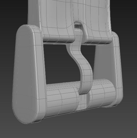
Using this picture I was able to model the watch clasp. I started by duplicating some of my already modeled geometry from the front panel of the watch and also duplicated part of the leather strap without holes.

I blocked out the middle metal tab first.

I then scaled it in various places; moving vertices as I went.
Here is the current version of the watch (almost there; I think)!
Current Amount of Time Modeling Watch Thus Far: 65 Hours

I next spent about another 3 hours bending the leather watch band and connecting the watch frame to the engine. My friend Tim suggested using the "FD 4X4X4" modifier (like the lattice tool in Maya) to bend the band (Thanks Tim!).


I decided that since I was running out of time (the project is already a week late) that I would just add the connecting side pieces and then start rendering it.

Here is the final model (for now; I might try to add a little bit to it later).

With the modeling completed I went on to a rendering program called "Key Shot". I spent about 8 hours with it playing around and adjusting lighting and textures and here are the results I got.


Time spent modeling and rendering: 76 hours.

Well that is another project finished, thank you for anyone who took a chance to glance at my work. I hope that some of my experiences shared with you may help you get some ideas about modeling and a few things you may be able to avoid to save time. Modeling the watch has helped me gain some new experience regarding modeling workflows and I now know that Key Shot is awesome haha. Check out my other blogs if you're interested! See you later!